|
|
|
|
Build a Stronger 2 Element Quad A Different way to construct a tried and true antenna out of PVC, especially for the 10 meter and higher frequencies. By KB3TTP (Updated Feb, 2012 - see bottom of article) Editors note: Quad antennas are notorious for being difficult to keep in the air. Following the ideas presented here by KB3TTP will enable your quad to be much stronger and to withstand the rigors of mother nature better. Although this project is for the 10 meter band, you can use these techniques for other bands also.
Welcome to a different way to construct a 2 element quad antenna for use on many radio frequency bands. Different because of it's support system and that it's constructed of all schedule 40 pvc pipe and fittings. The first thing you may think about is that it will never work without more rigid aluminum and fiberglass construction. I thought so too until I started playing with different designs and ideas. What resulted was a sturdy yet flexible design that held it's geometric shape extremely well and was very inexpensive to build yet light enough in fact that it can be turned by a common TV antenna rotor. The added "struts" to the 4 spreaders make this type of quad construction much stronger. I don't give geometric specifics because every band will have it's own dimensions. Parameters such as what part of the band you want your antenna tunned in at to take advantage of your preferred bandwith and even wire size you use will affect all the dimensions of the antenna. A good, yet easy to use antenna calculator for this can be found by clicking here. If you need help, send me an
email here KB3TTP AT comcast.net. Specifications: Approximate
Resonant Feedpoint Impedance =135.777 Ohms before added matching
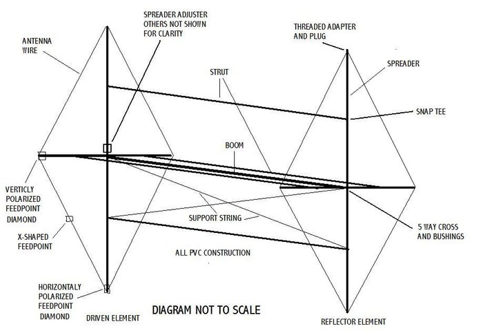
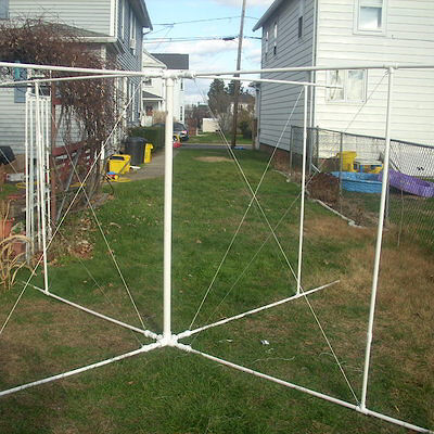
section. The Finished Quad. Boom height is at 29 feet configured in an X shape. The main mast is 2 1/2 diameter, 1/4 inch thick galvanized pipe. The secondary mast above the rotator is 1 1/2 inch steel tubing. A support bearing is used near the top of the secondary mast for extra strength and to protect the rotator. Primary coax is 8X low loss from the Wireman. An RG11 electrical 1/4 wavelength piece of coax is used as a matching section at the feed point. Extra struts were added to the quad as a different way to construct it from all pvc pipe and fittings. Antenna weighs only 21 pounds. Withstood 50 MPH winds. The mast to boom coupler is 8 X 12 inch 1/4 inch thick aluminum plate. There is a support cable at the top of the mast to keep the boom from flexing down at the ends over time. Construction
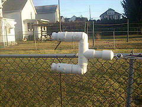
In the image above, you can see the antenna under construction. Note there is only one strut added at this point. The hardware and support strings and cable have not yet been added either. The next two images below, show the 1 1/2 inch 5
way cross assembly.
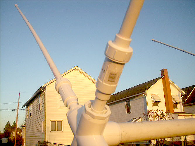
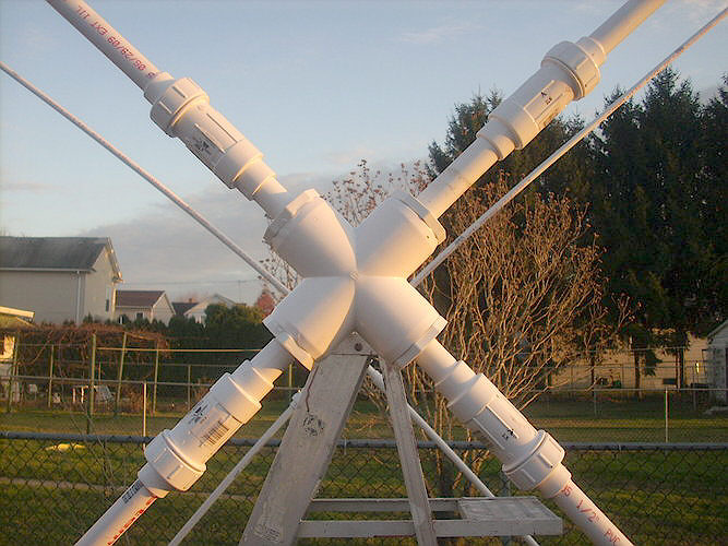
All joints are connected with pvc pipe cement. The telescoping couplings are cemented into the 1 1/2 x 1/2 inch bushings, then cemented into the cross. The assembly is attached to the boom also using cement. Boom is also 1 1/2 inches. It is from the center of this cross that you will be using to make some of your measurements for constructing the spreader arms. Don't cement your spreaders just yet. That will come a little later. When measuring to cut your boom you must take into account the depth at which it seats into the cross.
The image above shows one of the telescoping couplings or spreader arm adjusters extended to show you that you have approximately 2 inches of play when you extend these to tighten up your antenna wire. These are clamped off at their base to stop them from telescoping back in with stainless hose clamps. The one on the upper right has been extended. When making your measurments for cutting the spreader arms keep the adjusters compressed and subtract 1/2 inch from the total measurement to place the adjuster in the desired slightly slack position for the antenna wires. This image also shows the alignment between the two cross
assemblies. You only have a couple of seconds to align them when
cementing. An alternate method would be to bolt one of the crosses to the
boom if you feel you would like to do
so.
Now
you can cut your spreader to the desired length, keeping in
mind to take into account the distance the spreader arm fits into the
connector and the adjuster. The connector is a 1/2 inch slip X 1/2
inch
FPT.
In the photos above, you can see the simple attachment points for the support strings. A small hole was drilled in an area where there is a joint so that the medium sized eye screw can can catch both pieces of pvc for a strong hold. The cord used is a nylon masons string. (SEE UPDATE
BELOW) It is low stretch and very
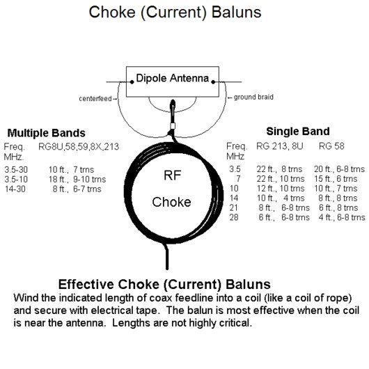
strong. Antenna Wire and Choke Coil An RF choke is
basicaly a current balun that divorces your antenna from the co-ax
cable. This is needed to keep all your power at the antenna and stopping
the co-ax from acting as a part of the antenna causing stray RF
emissions. In the drawing below are the coil
sizes and lengths of co-ax for various
frequencies.
Here is a link to a very good method of creating this choke. http://www.g0ksc.co.uk/creatingabalun.html Another good option would be to construct a 1/4 wave matching section out of 75 ohm coax. this would essentially convert the 135 ohm impedence in this antenna to approx. 50 ohms, as is desired. Take the formula that you have used on the home page to find your total wavelength for your design. Divide that by 4 and then multiply it by the velocity factor of the 75 ohm coax. This will give you the length of your matching section. Example: This antenna is designed for 28.400 mhz with 14 ga. wire. The wavelength is 415.588 inches, divided by 4 (quarter wave) = 103.897 in. Multiplied by the velocity factor of .66 of 75 ohm coax = 65.752 Inches. This is the length of your matching section using RG11 A/U.
The picture above shows the antenna feedpoint for an X shaped mounting which is what this antenna will be. Notice that it is the same design as for diamond shape. Also notice the two antenna wires between the stubs, ready to be soldered to the 75 ohm matching section. 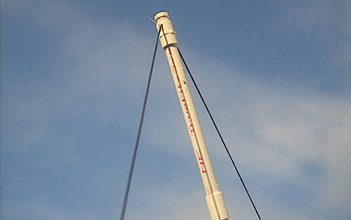 The picture above shows the wire strung through one of the spreader arms. All the wire I use in this project were purchased from "The Wireman". The antenna wire is 14 gauge Flexweave (trademark) and the coax is part #118 LO-LOSS 8X. The 75 ohm matching section described above is RG11 A/U 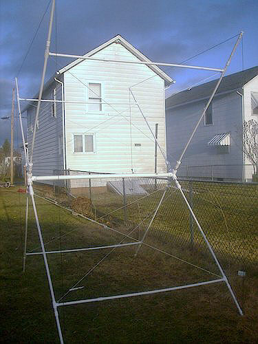 Wired and ready for mounting! Updates Feb, 2012 Explaination of the antenna
updates. B: The antenna used to twist on the
boom. Rotate back and forth would be a better explaination. The PVC flexed
in this manner but never broke under high winds. Not
acceptable.
C: The spreader arms saged in the hot
sun about 1/2 inch in the middle. Not much, but to much for me.
PVC and Sunlight Study What effect does ultraviolet exposure have on
PVC pipe? The results of the study indicate a gradual decline in the pipe's impact strength. The lowest impact strength recorded after two years of exposure was 158 ft-lbf, or 75% of the original ASTM value. These results indicate that no unusual handling problems should be expected from PVC pipe even after long-term exposure to sunlight. The study results also show that Modulus of Elasticity and Tensile Strength were virtually unaffected. The fact that these properties are unaffected signifies that structural integrity remain unchanged. UV degradation does not continue after installation when exposure to UV radiation is terminated. The presence of an opaque surface between the sun and the pipe prevents UV degradation, since UV radiation will not penetrate thin shields such as paint coatings or wrappings.. When exposure in excess of two years of
direct sunlight is unavoidable, PVC pipe should be covered with an opaque
material. Paint formulated to bond to plastics would be the best." See
the full report and study here. See his web site here!
 Hamuniverse.com uses Green Geeks Web Hosting! |