|
Tune
Around!
SEARCH
CQ-Calling All
Hams!
About Hamuniverse
Antenna Design
Antenna Safety!
Ask Elmer
About Batteries
Code Practice
Computer Help
Electronics
FCC
Information
Ham Hints
Humor
Ham Radio News!
Post Reviews
Product Reviews
Ham Radio Videos!
HF & Shortwave
License Study
Links
Midi Music
Reading Room
Repeater Basics
Repeater
Builders
RFI Tips and
Tricks
Ham Satellites
Shortwave Listening
SSTV
Support The Site
STORE
Vhf and Up
Contact
Site Map
Privacy Policy
Legal Stuff
Advertising Info
|
WA8CCU
2 Meter "Coax" Beam Project
Construction details of a 3 and 4 Element Coax
Beam
I had been looking for an inexpensive 2 meter
antenna project for some time.
One, I dislike buying an antenna when
one can be built for a reasonable cost.
Two, it is very
satisfying to construct an antenna and actually have it perform
well.
I discovered K4MMG's coax beam project on
Hamuniverse.com that really caught my attention, small, simple, looked
effective and very inexpensive.
So I built his 3 element coax beam and was very
impressed with the ease of construction and its performance. This led me
to the 4 Element version later in this article.
Steve,
(K4MMG), states in his article that he used an MFJ antenna analyzer, but
one could probably construct the antenna without
one.
Not having an antenna analyzer that
would cover 2 meters, I decided to construct anyway using a field strength
meter and an SWR bridge.
I mounted a pipe flange on the backyard
deck railing and used a 1/2" x 4' wooden dowel rod as a mast.
Total height of the beam off the ground was 10 feet.
Turning the beam
direction was by accomplished by
hand.

Base mount (Pipe
Flange)

2 Meter 3 Element Coax Beam
Tuning the elements for 146.0 was straightforward
using the SWR bridge and the FSM. Start with just the driven
element, tune, then add the reflector and tune it, then add the director
and tune it, etc.
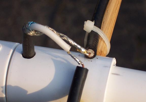
Driven Element construction.
Note:
NO connection to shield on either side of driven element!
(Refer to K4MMG's project for
details)

Coax outer connection during testing.
The field strength meter was placed on the deck
railing approx. 10feet away from the beam. Low power must
be used here, (about 1-2 watts) to keep the FSM from going
nutz.
After construction, I was able to make solid contacts to
about 80% of the local repeaters, (and some much more distant), but I did
notice that the front to back ratio of the beam could use improvement so I
proceeded with the 4 Element version described
below!
The 4 Element Coax
Beam
Conversing with Steve by Email I told him I was going
to try to add a second director and could he provide some starting point
as to distance from the 1st director and the length of the second director
element.
Steve willingly obliged and said although he had no
modeling program that would capture what I was trying to do, he thought
the same distance from the driven element to the 1st director could also
be used for the distance from the 1st director to the 2nd
director. He also felt that the 2nd director length
would be about 5% shorter than the 1st director.
I added a coupling
and more PVC pipe to the boom plus another dowel rod for the 4th element
at the suggested spacing. I also started the 2nd director coax
length the same as the 1st director.
I kept trimming the 2nd director
until the F-B ratio peaked sharply on the FSM in the forward
direction.
Wouldn't ya know it, 5.5% shorter than
the 1st director length was the length for the 2nd
director. Hereafter I refer to Steve as the
AG, (Antenna Guru).

4 Element 2 Meter Beam
Weather here in Northeast Ohio has degraded and
experimenting outside on the deck is not too pleasant, so I am using the
beam inside the shack about 4 feet off ground level and pointed
toward the window for one repeater 23 miles away, (total quieting), and
turned about 180 degrees toward another. Even though the 180 degree
direction points through walls, the barn and other sundry items, I make
solid contact with that
repeater about 12 miles away, all with 9
watts.
Odds & ends: First, I must acknowledge K4MMG, (the
AG), and his knowledge of coax behavior as an antenna. Second, this
is a very worthwhile project for any amateur seeking a good 2 meter beam
and the satisfaction of building his own.
Note that the pictures
show some nylon rope to the antenna. This was only to keep the
beam from sagging forward with the additional element.
The "T" for
the mast must be moved to a new boom balance position in the final
construction.
Also note that as I trim elements, I do not solder them just yet. I just wrap the
outer braid over the inner conductor and crimp gently with long nose
pliers. This is done in the interests of speed while tuning the
elements. Be sure to only use coax with a .66 VF. Solder ends of
coax after completion of testing and trimming.
SEAL ALL COAX ENDS AND CENTER FEED POINT
WELL.
In his article on the six meter beam,
Steve found that the frequency shifted down slightly when the coax
elements were removed from the dowel rods, (the prototype), and
inserted into a PVC "pipe", (the final construction). I expect
this will also be the case with this beam as well, but I have not
proceeded to that point yet as I am having too much fun with what I have
built at this time.
+++++++++++++++++++++++++++++
K4MMG does spec his element
spacing and lengths in his article.
I did not
change his spacing's as it gets too hard and complicated to
'juggle' both spacings and lengths while tuning.
But I did start with somewhat
longer elements as he states that element length will vary from builder to
builder.
Nomenclature: DE= driven element, DIR=
director, REF= reflector
Element spacing as
follows:
DE to REF....17.250"
DE to 1st DIR....13.250"
1st DIR to 2nd DIR=
13.250"
Final element lengths:
(Refer to the picture or K4MMG's construction detail.)
DE= 22.125"
(including the air gap)
REF= 24.000"
1st DIR= 21.500"
2nd DIR=
20.250"
It is important that elements be cut
about 1.5 to 2.0 inches LONGER when starting construction so there will
coax to trim back when tuning.
The DE should be alone on
the boom and trimmed first for lowest SWR at the desired operating
frequency.
Then add the REF to the boom and start trimming it for the
highest reading on FSM. When tuning the REF and both DIR's, the FSM should
always be sampling RF placed ahead of what will become the 'front' of the
beam.
Next mount the 1st DIR and tune it for highest FSM reading.
Do the same for the 2nd DIR.
Always maintain the same beam to FSM
setup for tuning elements. Do not move the FSM to different
distances or locations during element trimming or things become to
complicated.
To check the F-B ratio, turn the beam. Use only
enough power to get midscale FSM readings so differences between forward
gain and backside radiation can be easily determined.
Now get on
the air with yours and have fun....73 Al, WA8CCU

Monitor police, fire, ham
radio, rescue, ships and
more!

Hamuniverse.com uses Green Geeks Web
Hosting!
|
|
