|
Graphic Intensive!
Allow time to
load! |
The 4 band Broadband Hex beam
20-17-15-10 meters
By KE4NU -
Alan

Introduction
Wanted: HF beam, must be small,
light, inexpensive, easy to build, enter the Broadband Hex beam. I first
was introduced to a hex beam back in 2001 at the Huntsville, Alabama Ham
fest by a company call Traffie Technology (http://hexbeam.com/). It looked pretty impressive but I was moving to Montana so I
grabbed a brochure and filed it for future reference.
Living in
western Montana is great but usually all the eastern US stations beat me
in pileups trying to work Europe on 20 meters and higher bands. I thought
it might be time to replace the little 20-6 meter hybrid quad that had
served me well for several years with something that had a little more
gain and not much more weight and wind load. I started searching the web
for potential candidates. I came across the hex beam users group (http://groups.yahoo.com/group/hex-beam/). After seeing the prices on the commercially made hex beam I
knew I’d never talk the xyl into that so I started searching for
alternatives. I saw several web sites that were dedicated to the
construction of a home made multiband hex beam. It looked pretty hard to
build but I kept at it, studying and learning as much as possible about
the hex beam. I then noticed several posts about a Broadband Hex Beam
being developed by G3TXQ that had more gain and was much easier to build.
Hey, this could be the one.
I would recommend anyone interested in
this antenna to go to (http://karinya.net/g3txq/hexbeam/) where you will find a wealth of knowledge by G3TXQ or Steve
who is the father of the BBHB (Broadband Hex Beam).
After gaining
a stronger understanding of the antenna I went to Leo’s website (http://leoshoemaker.com/hexbeambyk4kio/general.html) who has presented an easy to follow step by step instructions
on building this antenna and I highly recommend it. I left off the 24 MHz
band because of the likelihood of interaction and I’d never had much
interest in that band anyway. If you want this band by all means go ahead
and add 24 MHz, I just decided not to. So instead of the 5 band described,
I was going to build a 4 band version of the G3TXQ
BBHB.
Step one: Gathering the parts
To get all the parts and materials
as outlined in Leo’s plan proved to be the most challenging of this whole
project. Now, its easier with more sources so don’t be scared
off.
I got the spreaders off eBay to save a few bucks.
I found the base plate locally but it was a little thicker than
called for and that changed a few bolt lengths and made it a bit heavier.
I got a local ham friend (W8QMD) who runs a machine shop to score and mark
the plate for me. Now you can order the base plate already drilled in
different levels of completeness from (http://hexkit.ronmott.net/).
Also you can order the spreaders from (http://www.mgs4u.com/hexbeam-kit.htm).
You can find some of the parts locally such as clamps,
bolts, electrical PVC conduit. You may have to order the 16 gauge
wire, Dacron and Kevlar rope from other sources such as http://www.thewireman.com and http://www.radioworks.com.
The connectors come from Radio Shack; I could never
find them from any other source in the jumbo size.
Just follow
Leo’s parts list and you won’t go wrong. Expect to fork out 200 to 300
dollars if you have to purchase everything. I scrounged as much as
possible so I saved a few bucks along the way, but sometimes cheaper in
not necessary better.
Step two: Construction
I followed Leo’s plans to the
letter and did not deviate from it until construction was nearing
completion and I saw some improvements I could implement. I strongly
advise you to do like wise. Leo was a great help when I emailed him with
questions and he was quick to respond.
I started by drilling holes
in the base plate and mounting the flange to it.
Then I
inserted the 1 1/4 inch electrical PVC conduit through the center
hole and securing it in place.
I then took the fiberglass
spreaders and measured them out to proper length and painted them flat
black to reduce UV damage.
I also used schedule 40 1 in diameter
PVC sections cut in about 5 inch lengths on the base plate so the
spreaders could go inside of them to keep from tightening down directly on
the fiberglass. I also painted these black. I attempted to glue the
spreaders together with liquid nails but this didn’t work very well. So, I
drilled a small hole through the spreaders where they joined together and
put a small screw with a flat washer at both ends. This proved to work
well and they didn’t move at all.
After putting clamps at the
designated places on the spreader I set the spreaders
aside.
Next, I measured out the wire to the specified
lengths. This proved to be challenging by myself but after triple checking
I had the correct measurements for the 4 bands I wanted, both director and
reflector per band.
Then I made the end spacers (two for each band)
using small dacron rope and the radio shack
connectors
I carefuly coiled up each wire and
labeled them and set them aside for later use. I then measured and drilled
the holes in the center mast.
I followed that by making up the
harnesses to go from band to band.
The antennas feeds from the top
with 20 meters being first, then 17, 15 and finally 10 meters just 6
inches above the base plate.
I drilled a hole in the base
plate to run the feed line through, then ran it up the opposite side of
the feed point connections and over the top of the center post and
connected to the 20 meter feed point.
To get the screws inside the
center mast and protruding through each respective hole took a little
time. Leo recommended a metal clothes hanger which I didn’t have. I tried
10 gauge wire looped around the screw once and that worked for the 20
meter holes. The wire was too flexible and bent when I tried to get the
other screws through their respective holes. I ended up finding an old
fiberglass antenna (probably 11m) and taped the 10 gauge wire to it. In 5
minutes I had it done.
I then inserted the short 1” PVC sections
in the u-clamps and then inserted the spreaders in each one respectively
and tightened them but not too tight.
Make sure to install
lock washers on the u-clamps.
Next I made up the 130 inch nylon
sections of rope including s-hooks on each end. I used bailing twine since
I had plenty lying around and it worked great.
Then I started
installing the cords with 6 radial cords first as Leo’s plans suggest and
then install the perimeter cords. You’ll find it incredibly easier to
install the wires in the beam if you have it pulled up to proper shape.

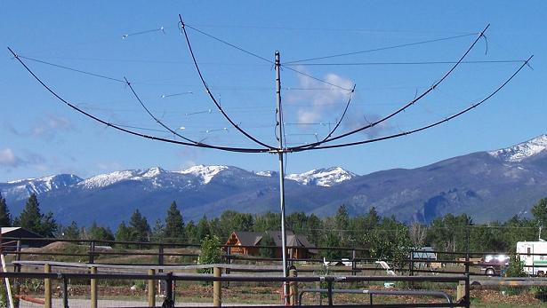
The HexBeam Spreading it's wings in beautiful
country!
Next, install
your 20 meter driven element and reflector. You should make sure each half
of the director extends 128 inches out from the center post to each
connector and then tighten down on wire with the set screws. I made a 128
inch measuring stick out of 2 pcs of fiberglass.
After securing
the director, install the reflector making sure there is 128 inches
between all spreaders and center post to connector or corresponding clamp
by using lengths of dacron rope. Also add the 2 shorter lengths of dacron
rope on the front side of the director (this is the front of the beam).
After achieving 128 in spacing screw all the remaining connector screws
down to hold it in position.
Once you achieve that
tighten down on all the connectors to hold the exact measurements and
shape. Then take off the supporting nylon cords. The 20 meter antenna now
holds the shape of the antenna.
I had about 2 ft of center post
extruding out the bottom of the base plate. I placed this in a 5 gallon
plastic bucket containing several large rocks. This let me have the
antenna low enough to the ground so I could work on and install all the
elements. Once all were installed, I used a rather large wooden reel
used for wire or cable on its side.
This let me do preliminary testing
of the antenna.
Step 3: Testing
Finding a suitable mast that the
plastic center post would slide into proved to be a challenge. I finally
took a piece of the pvc to a fencing company and found one. It was marked
20SS. I attached the 10 ft pipe with the hex beam on top to a fence post.
Antenna mounted on fense post for
testing.
The beam performed fairly well
even at this height. Resonance points were on the low end of each band.
The antenna tested very broadband and had good side and back rejection. I
expected the resonant frequencies to rise when put up to at least a 1/4
wavelength and they did for all bands.
Back down to the bucket
again so I could strengthen clamps and connections. I wrapped Dacron rope
tightly around the connectors that held a lot of tension (20 meters).
I noticed a little splitting in the spreader junctions and I
installed hose clamp to help prevent this. I doubled up on the plastic
ties on the non tensioned connectors.
I got an 8 in piece of 4
inch PVC drainpipe and made a choke by wrapping 7-8 turns of RG-8X around
it and mounted it to the bottom of the base plate.
I checked
Dacron cord measurements and had to readjust for
stretching.
Everything now looks good so back on the fence
post and made a few contacts including some dx.
I decided to let
it sit there for about a month to give it a chance for anything to
stretch, break or come undone. Patience is a great virtue. Don’t get in a
big hurry with this antenna.
Step 4: Installation
I got several friends together on a
nice day with a winch mounted on a UTV. I put a pulley about 20 ft in a
tree and connected the winch cable to a strong rope I had tied around the
tower.
I took the guys loose and the bolts out at the bottom and
we laid it over within a few minutes. This shouldn’t take long I thought,
wrong! The mast would not fit through the tube in the top of the Rohn AG25
so it could mate up with the rotor. The mast was too thick.
I
quickly called on W8QMD again and he made an adapter pin that would fit
down through the top section tube and would let the antenna mast slide
over it. That solved that problem.
I hinged the tower up so the
top would be about 10-12 ft off the ground. I then positioned an 8 ft step
ladder so I could walk the BBHB up the ladder and mount it to the adapter
pin. It went off without a hitch except sore muscles from lifting and
straining the antenna above my head. We winched the tower back up and
checked the swr, and it was very good.
I connected the coax to the
radio and made a few contacts. I had excellent results with the
beam headed SSW. It was 3-5 S units better than my loop. I then tried to
turn the antenna and it didn’t turn. I took for granted since the rotor
turned before I brought the tower down that it would continue to work, not
the case. I finally got a new Yaesu G-450 rotor.
I rented a man
lift that went to 42 ft and on a warm Nov day I changed out the rotator
and it works fine. My first contacts were DU2, BX5, and I was running low
power.
SWR was not over 1.2 to 1 over all bands covered except the
upper end of 10 and it approached 2 to 1 at 29.6.
As a bonus, it also loaded easily on the 30 meter
band and the 6 meter band with my built in tuner on the 746
pro...

Up in the air!
In
Conclusion!
This was the most complicated
antenna I’d ever built but well worth the effort. If you’re considering
one, do the research on the above web sites and forums; gather your parts
then go for it. This is going to be a super antenna and I built it myself. Feel free to contact me with any
questions but please refer to the web links above
first.
http://montanaham.tripod.com/
ke4nu7 AT gmail.com
73, KE4NU - ALAN